
 español



Performance analysis and optimization of high-voltage energy harvesting current transformer (4)
In our previous discussion, we Analysis the optimization of magnetic core parameters. Today, we will proceed with the Core saturation prevention design .
3) . Core saturation prevention design
After the magnetic core saturates, the load voltage waveform distorts and exhibits a spike waveform. Voltage spikes may damage the circuit, while the magnetic core generates heat and vibrates, causing serious harm to the magnetic core.
3.1 Analysis of turns variation
According to the analysis in Section 2, selecting an appropriate number of turns can enable the magnetic core to achieve the maximum power value. In order to enable the magnetic core to operate normally under a high current, the number of turns of the secondary winding can be changed to deviate its output power from the maximum power point, thereby preventing saturation.
After simulation testing, when the load is 100 Ω and the matching secondary winding turns are 100 turns, the maximum tolerable primary current is 50 A. At this time, the magnetic core deviates from the linear working area, and the secondary voltage waveform is slightly distorted, but it does not affect the normal operation of the load. Due to a load of 100 Ω, the number of test turns must be at least greater than 100 turns.
The magnetic core parameter settings are shown in Table 1. The load is set to 100 Ω, the primary current I1 is set to 50, 100, 200, 300, 400, 500 A, and the number of turns of the secondary winding is set to 100-500 turns. The simulation results are shown in Figure 10.
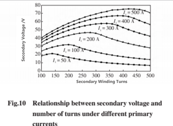
By organizing the information in Figure 10, the unsaturated turns and output voltage data under different primary currents can be obtained, as shown in Table 2. In the table, U2 is the secondary side output voltage; Nt is the number of turns when the magnetic core exits saturation.
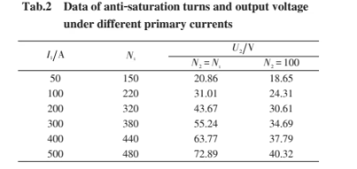
From the above analysis, it can be concluded that increasing the number of turns in the secondary winding can limit saturation. However, due to the poor saturation performance of nanocrystalline magnetic materials, at a current I1=500 A, the number of turns in the secondary winding needs to be at least 480 to cause the magnetic core to exit saturation.
3.2 Load variation analysis
From the above analysis, it can be seen that changing the number of winding turns alone still weakens the anti saturation performance of the magnetic core, and can only withstand a current of about 500 A. According to equation (8), changes in the number of turns and load will cause the power to deviate from the maximum value. Meanwhile, observing Figure 9, compared to changing the number of turns, changing the load has a greater impact on the saturation performance of the magnetic core.
Both larger and smaller loads can cause power offset, but when the load is too high, the secondary voltage increases and the power demand is also higher, which may cause trouble for subsequent processing circuit design. Therefore, reducing the load is adopted to make the power deviate from its maximum value.
Therefore, this article proposes a parallel resistance strategy, and the equivalent circuit is shown in Figure 11. The smaller parallel resistance R reduces the equivalent load Rt, resulting in a decrease in the voltage of the load RL. At the same time, the overall power demand is greatly reduced, and the magnetic core is less prone to saturation.
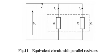
According to Figure 11, the expression for load current I22 is

According to equation (12), the parallel resistance R cannot be too small, otherwise the current flowing through the load may be too small, which may lead to insufficient power supply.
Set the parallel resistance to 5Ω, the number of turns of the secondary winding to 100 turns, and the load to 100Ωfor simulation analysis. At this time, the magnetic core still experienced saturation when the primary current was 1000 A. The simulation results are shown in Figure 12.
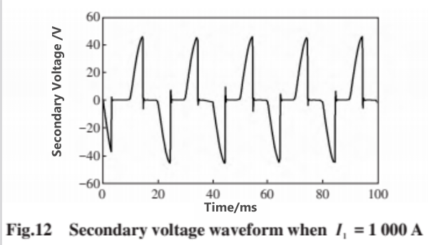
The above analysis indicates that simply using the strategy of turns transformation or load transformation cannot solve the power supply problem of a large current.
3.3 Methods for Core Saturation Suppression
In this design, the small-current power extraction performance is considered first, which results in a weak anti-saturation capability of the power-extracting core. Using a single saturation suppression method, the CT cannot adapt to large fluctuations in primary current. To address this, a combined method of multi-turn strategy and parallel resistance strategy is proposed.
From the above analysis, it can be seen that when RL = 100 Ω, the change in the number of turns has a relatively small impact on the offset of the power extraction power, while the change in load has a greater influence. From Equation (12), it is known that the smaller the parallel resistance R, the less power the load RL obtains. Therefore, to increase the load power, the parallel resistance R should be as large as possible within the selectable range, and a larger number of turns should be selected to reduce the current in the parallel circuit and lower the difficulty of hardware design.
From the above analysis, combined with Equation (8), the parallel resistance value should at least meet the following conditions
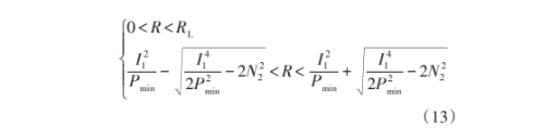
In the formula, Pmin is the minimum power available to the load. Considering the size limitations of the hardware housing, the maximum number of turns for the secondary winding is 500. Test the impact of the parallel resistance on the core saturation capability. The parallel resistance R is set to 5, 10, 15, 20, 25, and 30 Ω, and the primary current is set to 500, 1000, 1500, 2000, 2500, and 3000 A for simulation analysis. The simulation results when the primary current I1 = 1500 A are shown in Figure 13.
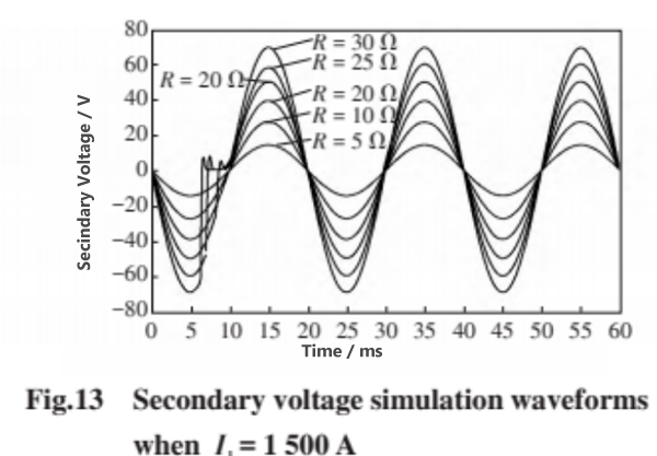
From the simulation results, it can be seen that using a combined strategy of multiple turns and parallel resistors, the magnetic core will not saturate in most cases. By analyzing the simulation results, the anti saturation performance data of the magnetic core after load parallel resistance can be obtained, as shown in Table 3, where Rmax is the maximum parallel resistance.
According to the data in Table 3, when the parallel resistance is 15 Ω, even if the primary current reaches 3 kA, the magnetic core does not saturate; When the parallel resistance is 20 Ω, the secondary voltage waveform begins to distort, but the degree of distortion is not severe. Therefore, in this design, a parallel resistor of 15 Ω can be selected, and the magnetic core can withstand a primary current of 3 kA and operate stably. Meanwhile, data analysis shows that as the parallel resistance decreases, the primary current that the magnetic core can withstand increases. If smaller parallel resistors are used within the allowable design specifications, theoretically the magnetic core can withstand a larger primary current and operate normally.
3.4 Control Strategy
For the convenience of subsequent hardware circuit design and to reduce the difficulty of program design, the selection of turns and parallel resistors needs to meet the fixed resistance value of high current energy harvesting index, which is easy to control and not prone to faults. The control steps are as follows:
Step 1: When the current is less than 50 A and the magnetic core is not saturated, select 100 turns and do not connect a parallel resistor to maximize the power output;
Step 2: When the current is between 50~500 A, according to the analysis conclusion in Section 3.1, switching the number of turns to 500 turns without connecting parallel resistors can cause the power point to deviate from the maximum value, prevent the magnetic core from saturating, and obtain a larger power;
Step 3: When the current is between 500~3000 A, based on the conclusions in Table 3 and Section 3.3, it can be concluded that 500 turns can still be selected, and a 15 Ω parallel resistor can be connected. The maximum power point deviates further from Step 2, and the magnetic core exits the saturation working zone. Under the control of this method, the magnetic core always operates in the linear working region without saturation within the range of a primary current I1<3000 A.
Categorías
Nuevo blog
Para obtener consultas sobre nuestros productos o su lista de precios, por favor, déjanos a nosotros y estaremos en contacto dentro de las 24 horas.


 Llama a :
Tel : +86-20-85649266
Fax : +86-20-85649263
 Envíanos un correo electrónico :
Correo electrónico : derful@coilcore.com
 Dirección :
A402 Zhuangyuangang Industry Park, No.186 Qishan Road, Tianhe District, Guangzhou 510663
© Derechos de autor: 2026 Guangzhou Amorphous Electronic Technology Co.,ltd. Reservados todos los derechos. 粤ICP备2021057165号

Red IPv6 admitida
Enlaces amistosos:
Precision Air Conditioning wellav syblecode gangyuantech PCB Board eavisionag PLC liantronics kenmold 5gplc Mu Metal Core Manufacturer PLC modules liantronics Customized Filter Supplier tslcd szgilong addbuyplc ifpdtech dtechelectronics sekloadcell naturollsensor smarts-electronics bnttablesocket mbluetech esdled oscymonitor current sensor zhicetemptech benchu-group esdled